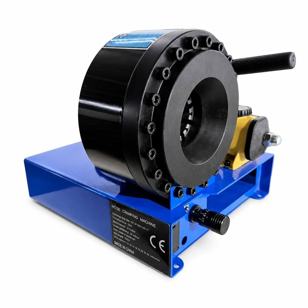
A hydraulic crimping machine is an industrial tool designed to apply precise, uniform pressure for joining hoses, fittings, and connectors through deformation. Unlike mechanical presses that rely on manual force or electric motors, these machines use hydraulic fluid pressure to generate consistent, repeatable crimping force. Understanding how a hydraulic crimping machine functions is essential for industrial operations, plumbing installations, automotive assembly, and hydraulic system maintenance where airtight, durable connections are critical.
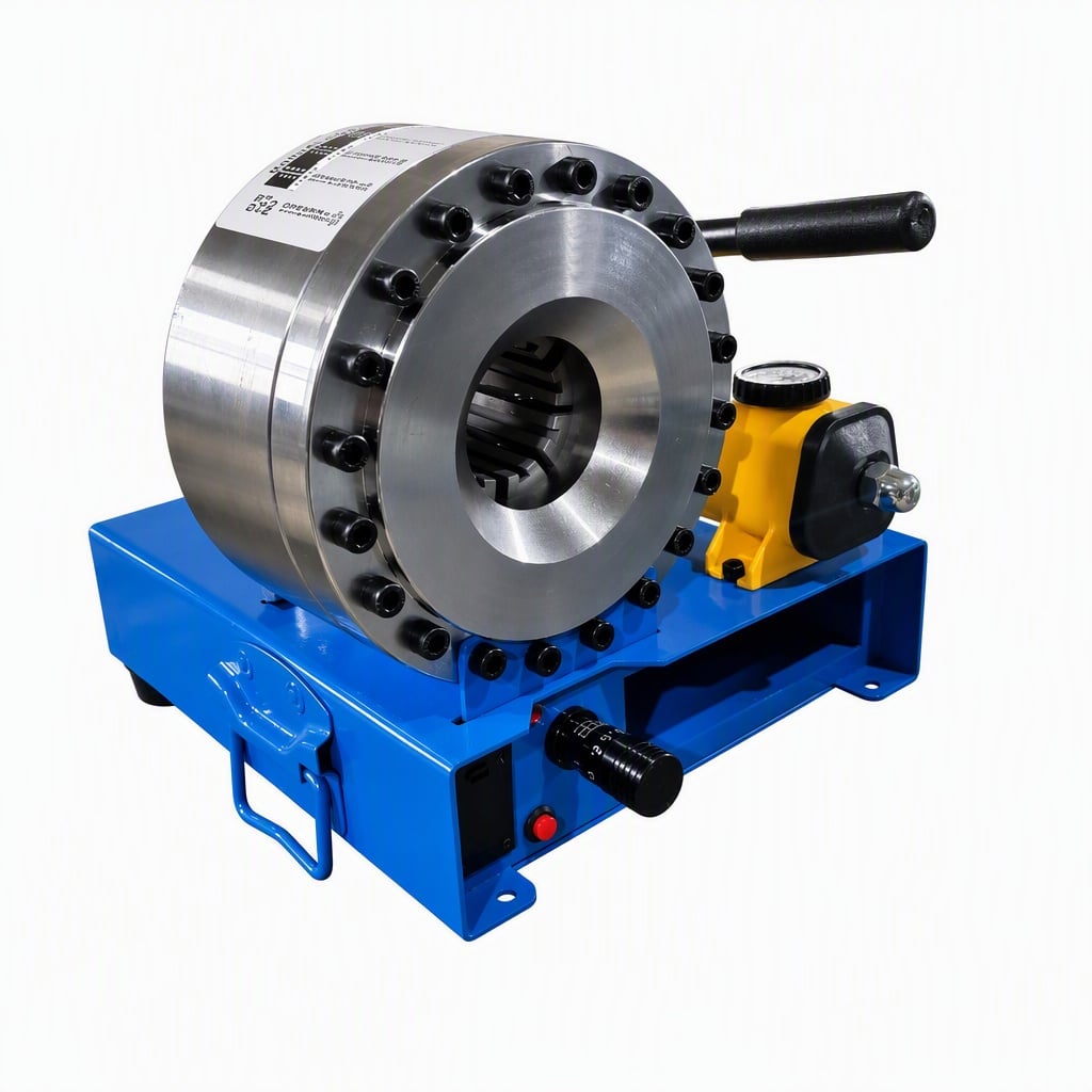
The fundamental principle behind these systems involves converting hydraulic pressure into linear or rotational mechanical force that compresses metal sleeves onto hose barrels and fittings. A hydraulic crimper tool operates through a coordinated sequence of fluid pressure, mechanical translation, and die positioning to achieve professional-grade results consistently. This technology has become the industry standard because it minimizes operator skill variation, reduces rework, and delivers crimps that meet or exceed ISO 1402 and SAE J343 standards for hose assembly integrity.
Core Components and Hydraulic System Architecture
Hydraulic Power Generation and Fluid Circuit
The hydraulic system begins with a pump that draws hydraulic fluid from a reservoir and pressurizes it to operating levels, typically between 700 and 3,000 PSI depending on the crimping press equipment classification. A motor, electric or pneumatic, drives this pump continuously or on demand. The pressurized fluid travels through steel hoses and passages to control valves that regulate flow direction, pressure relief, and intensity adjustments. Directional control valves allow operators to activate the crimping cycle, raise the upper platen, or return to neutral positions. Pressure relief valves protect the entire circuit by venting excess fluid if pressure exceeds safe thresholds.
Cylinder and Linear Force Delivery
At the heart of the crimping action sits a hydraulic cylinder, typically a double-acting unit with a piston rod that extends and retracts. When the operator initiates a crimp cycle, pressurized hydraulic fluid flows into the cylinder's cap-end chamber, pushing the piston and rod downward with tremendous force. The hose fitting crimper uses this linear motion to drive the upper die or crimping head down onto the component resting on the lower die. The cylinder's bore diameter, rod diameter, and system pressure determine the total output force. For example, a cylinder with a 4-inch bore at 2,000 PSI generates approximately 25,120 pounds of force, sufficient to deform metal sleeves permanently around hose barrels without generating excessive heat or material fracture.
Die Assembly Mechanics and Crimping Geometry
Die Design and Sizing Standards
Dies are precision-engineered tool steel components that shape the crimp profile. Every hose fitting crimper system includes matched upper and lower dies calibrated to specific hose sizes, fitting styles, and sleeve dimensions. The die cavity matches the nominal diameter and contour of the component being crimped, ensuring that metal flows uniformly around the hose barrel and forms a secure, leak-proof seal. Dies are typically designed with progressive or synchronized profiles so that the crimp develops symmetrically from outside toward the center, minimizing internal void spaces. Professional crimping press equipment incorporates quick-change die systems that allow operators to swap dies in seconds without requiring extensive adjustment or calibration, improving workflow efficiency across multiple hose sizes and applications.
Pressure Application and Dwell Time
During the crimping cycle, the hydraulic cylinder applies its maximum force gradually or instantaneously, depending on the machine's control logic and valve configuration. Most modern systems employ pressure-time profiles rather than fixed-displacement cycles. The hydraulic crimping machine may hold maximum pressure for 1 to 3 seconds, called the dwell period, to allow metal fiber consolidation and stress relief within the crimp. This dwell prevents springback and cracking that occur if pressure is released too quickly. Pressure sensors and electronic controllers monitor actual force application and terminate the cycle only when crimping parameters are met. Microprocessor controls on advanced hose fitting crimper equipment log each cycle, flag incomplete crimps, and maintain records for quality audits.
Operational Workflow and Safety Integration
Cycle Sequence and Operator Interface
A typical hydraulic crimper tool cycle begins when the operator positions the hose and fitting assembly on the lower die, aligns it visually or with mechanical guides, and initiates the cycle via a foot pedal, button, or touchscreen interface. The hydraulic system energizes, and the piston rod extends downward, accelerating under pressure until the dies make contact. Once contact is detected through pressure feedback, the system transitions to a controlled compression phase where force increases steadily to the target crimping pressure. After the dwell period completes, a solenoid valve opens the return circuit, allowing spring pressure or pilot-operated mechanisms to retract the upper die. The operator removes the completed crimp and repeats the process. This cycle typically takes 10 to 30 seconds depending on component size and machine sophistication.
Safety Systems and Pressure Monitoring
Industrial crimping press equipment incorporates multiple safety layers to prevent operator injury and equipment damage. Pressure relief valves limit system pressure to a preset maximum, protecting hoses, cylinders, and seals from rupture. Two-hand controls or motion-sensing mats ensure operators keep hands clear of the die area during compression. Load cells beneath the lower die detect abnormal resistance that might indicate a misaligned component or foreign object, triggering emergency stops. Hydraulic accumulators store energy to smooth pressure spikes and protect delicate control electronics. Regular maintenance of the hydraulic crimping machine—including fluid analysis, seal inspection, and pump performance testing—ensures consistent operation and extends system life to 15 to 25 years in demanding industrial environments.
Frequently Asked Questions
What pressure levels does a hydraulic crimping machine typically operate at?
Most hydraulic crimper tool systems operate between 700 and 3,000 PSI, with the majority of general-purpose models standardized around 1,500 to 2,500 PSI. The exact pressure depends on the hose size, fitting design, and material hardness. Larger diameter hoses and steel sleeves require higher pressures to achieve permanent deformation. Industrial crimping press equipment may offer adjustable pressure settings to accommodate different application requirements, while compact or portable units often use fixed-displacement pumps. Always consult the machine manufacturer's specification sheet to ensure proper pressure settings for your specific hose fitting crimper application.
How do I know if my hydraulic crimper tool is applying sufficient pressure?
Professional hydraulic crimping machines include pressure gauges or digital displays showing real-time system pressure during each cycle. You can also inspect crimp quality visually—a properly crimped connection shows uniform metal deformation around the barrel, no visible wrinkles or gaps, and smooth surface texture. If you suspect under-crimping, pull-test samples to verify hose-fitting integrity. Over-crimping may cause hose damage or fitting fracture, evident from cracks or permanent set marks. Many modern hose fitting crimper systems log pressure and force data electronically, allowing you to trend cycles and identify when maintenance is needed or pressure adjustments are required.
Can a hydraulic crimping machine handle different hose sizes with one die set?
No, each die set is manufactured for a specific hose and fitting combination. A crimping press equipment designed for 1/4-inch hose will not produce acceptable crimps for 1/2-inch or 3/8-inch hose because the die cavity dimensions and sleeve profiles differ. However, most professional hydraulic crimper tool systems use interchangeable quick-change die blocks, allowing operators to swap dies in under a minute without removing the upper platen. Maintaining multiple die sets for common hose sizes ensures flexibility and minimizes downtime during production runs or mixed-application workdays.
 EN