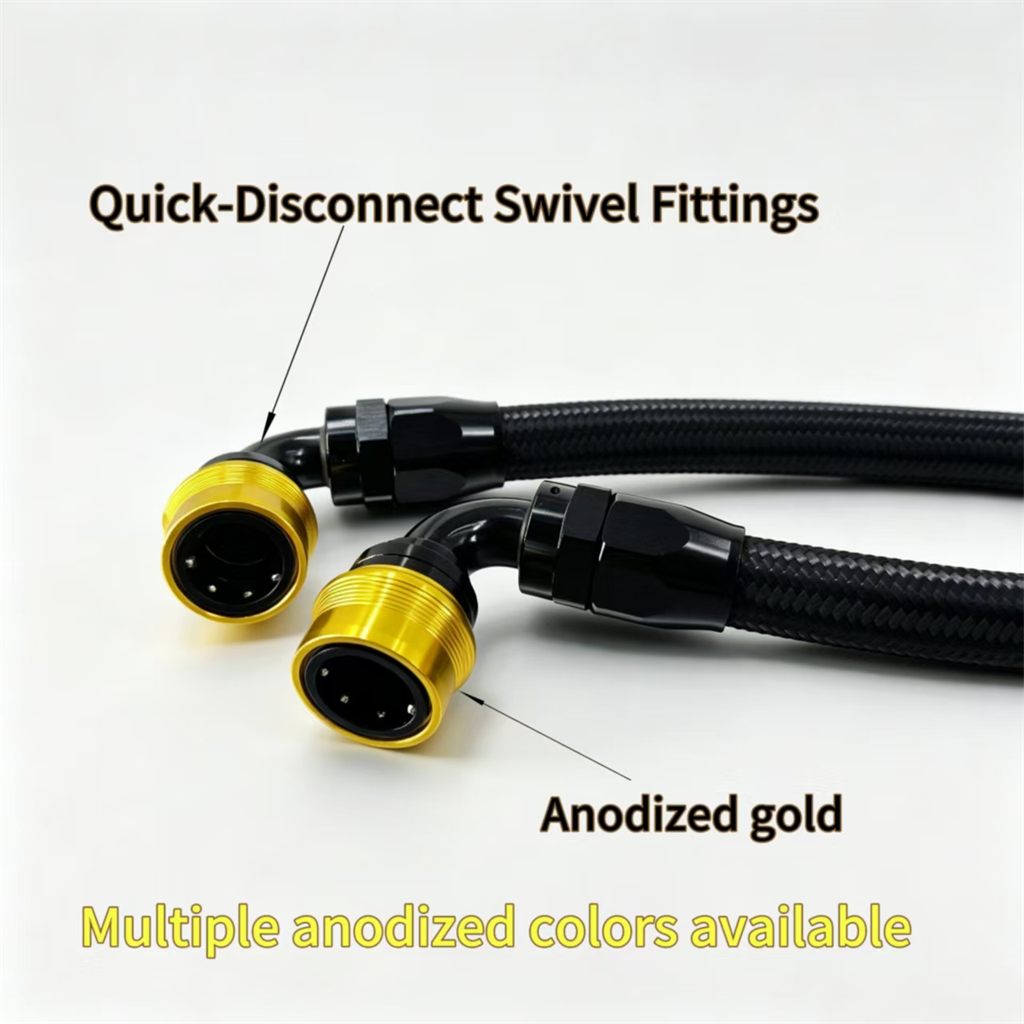
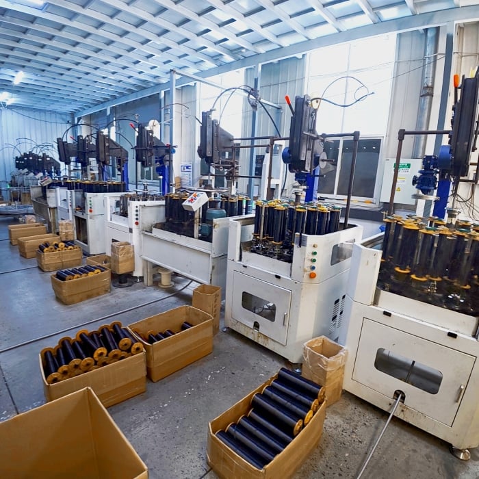
Selecting the correct hose assembly size is critical to the performance, safety, and longevity of your fluid transfer systems. Whether you operate in manufacturing, construction, agriculture, or any industrial sector, an undersized or oversized hose assembly can lead to pressure drops, system failures, leaks, and costly downtime. The right size ensures optimal flow rates, minimizes energy loss, and protects downstream equipment from damage.
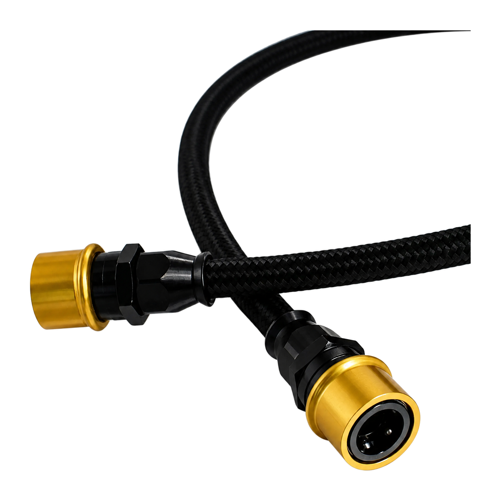
Understanding the core principles behind sizing a hydraulic hose assembly, hose fitting assembly, and industrial hose system requires knowledge of flow rates, pressure ratings, fluid velocity, and diameter calculations. This guide walks you through the essential factors that determine proper hose assembly sizing, enabling you to make informed decisions that align with your operational requirements and industry standards.
Key Factors in Determining Hose Assembly Size
Flow Rate and Velocity Requirements
Flow rate is the volume of fluid traveling through your hose assembly per unit time, typically measured in gallons per minute (GPM) or liters per minute (LPM). The hose assembly diameter must accommodate this flow without causing excessive velocity, which accelerates wear and generates heat. Industry standards recommend fluid velocity between 4 to 6 feet per second for general hydraulic applications, though specific applications may vary. When designing a hydraulic hose assembly, engineers calculate the required internal diameter by dividing the flow rate by the target velocity. An oversized hose assembly wastes material and increases installation complexity, while an undersized one creates backpressure and reduces system efficiency.
Pressure Rating Compatibility
The pressure rating of your hose fitting assembly must exceed the maximum operating pressure of your system by a safety margin, typically 25 percent or more. Higher pressure systems often require smaller diameter hoses with reinforced wall thickness to handle the stress safely. When selecting a hose assembly, always cross-reference both the diameter and pressure rating specifications against your system requirements. A hose fitting assembly rated for 3000 PSI differs fundamentally from one rated for 5000 PSI, even if both share similar diameters. This relationship between pressure and diameter makes pressure specification equally important as sizing the industrial hose system correctly.
Understanding Industrial Hose System Architecture
System Layout and Component Integration
An industrial hose system consists of the hose assembly, hose fitting assembly, connectors, and integration points within your equipment. Before sizing, map out your system layout to identify where the hose assembly will operate and what components it must connect. Temperature conditions, exposure to chemicals, and ambient environment all influence material selection and therefore performance characteristics of your hose fitting assembly. For example, a hose assembly running through extreme heat requires different construction than one in a cooled facility. The industrial hose system must maintain integrity across all operating conditions while delivering the specified flow rate without pressure loss.
Pressure Drop Calculations
Pressure drop occurs as fluid travels through the hose assembly due to friction and turbulence. Longer runs, smaller diameters, and higher viscosity fluids all increase pressure drop. Engineers use formulae and hydraulic software to calculate expected pressure drop for a given hose assembly size, flow rate, and fluid type. Acceptable pressure drop in a hydraulic hose assembly typically ranges from 2 to 5 percent of system pressure. If calculated pressure drop exceeds this range, you must increase the hose assembly diameter to reduce resistance. This trade-off between initial hose fitting assembly cost and long-term energy efficiency guides sizing decisions in industrial hose system design.
Practical Sizing Methodology for Your Hose Assembly
Step-by-Step Sizing Process
Start by gathering your system specifications: maximum flow rate in GPM or LPM, maximum system pressure, fluid type, hose assembly length, and environmental conditions. Use the formula Diameter = sqrt(4 × Flow Rate / (π × Velocity)) to calculate required internal diameter, where velocity is expressed in feet per second. This calculation yields the minimum hose assembly diameter needed for your hydraulic hose assembly. Next, cross-reference this calculated diameter against standard hose sizing charts to find available hose fitting assembly options in standard sizes like 3/8 inch, 1/2 inch, 3/4 inch, or 1 inch. Select the smallest standard hose assembly that meets or exceeds your calculated diameter, then verify that the pressure rating accommodates your system requirements with appropriate safety margin.
Real-World Application Adjustments
Laboratory calculations provide a foundation, but field conditions often require adjustments to hose assembly sizing. If your industrial hose system includes long runs of hose assembly exceeding 100 feet, consider upsizing by one standard size to compensate for increased pressure drop over distance. Similarly, if your hose fitting assembly must handle variable flow rates or pressure spikes, verify that your selected size handles peak conditions, not just average operating parameters. Temperature fluctuations affect fluid viscosity, which impacts both pressure drop and the performance of your hose assembly. Cold fluid becomes thicker and generates higher pressure drop, so environments with temperature swings may demand a larger hose assembly diameter than warm-climate applications. Field experience with similar hose fitting assembly installations provides valuable guidance for refining your industrial hose system sizing beyond theoretical calculations.
FAQ
What happens if I choose a hose assembly that is too small?
An undersized hose assembly creates excessive fluid velocity and pressure drop, causing system inefficiency, heat generation, and accelerated wear on the hose fitting assembly and pump. The hose assembly may fail prematurely, and your equipment may not perform at rated capacity. High velocity fluid in a small hose assembly also increases noise and vibration, potentially damaging connected components.
Can I use the same hose assembly size for different pressure ratings?
While a hose assembly diameter may remain constant, the pressure rating depends on wall thickness and reinforcement layers of the hose fitting assembly. A hose assembly rated for 2000 PSI is structurally different from one rated for 5000 PSI, even at the same diameter. Always verify that your hose fitting assembly's pressure rating matches your system requirements, not just the diameter. Assuming equivalent performance based on diameter alone creates a serious safety and reliability risk in your industrial hose system.
How often should I recalculate my hose assembly sizing?
Recalculate your hose assembly sizing whenever you modify system flow rates, pressure settings, fluid type, or hose assembly length. Changes to any of these parameters affect the sizing calculation and may require upgrading your hose fitting assembly to a larger diameter or different pressure rating. Additionally, if your industrial hose system experiences frequent pressure drop issues or inefficiency, review the original sizing calculation to identify whether the current hose assembly is truly appropriate for evolved operating conditions.
 EN