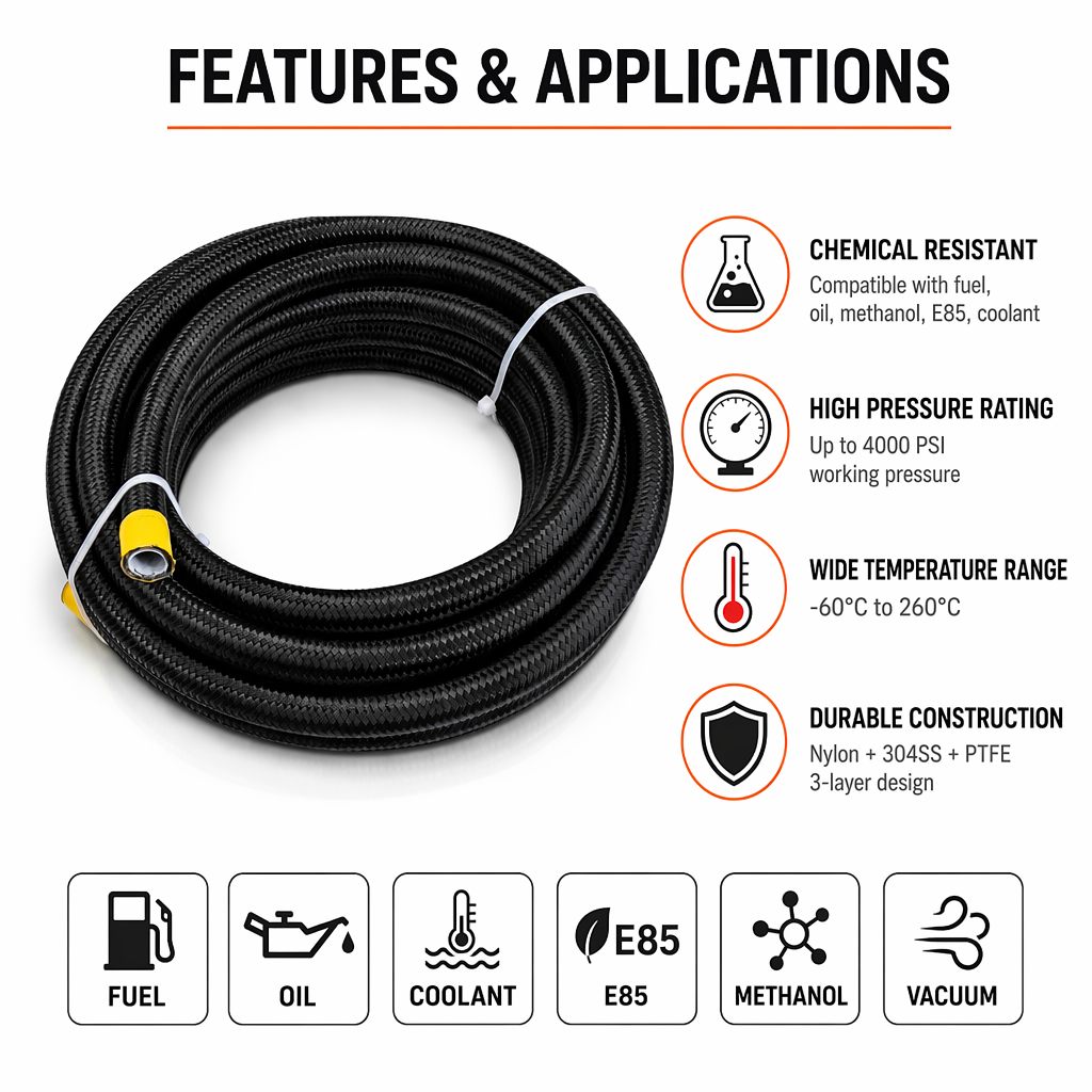
Choosing the correct diameter for a teflon hose is one of the most critical decisions in fluid transfer system design. The wrong diameter selection can compromise flow efficiency, create pressure drops, cause system failures, or waste material costs. Whether you're working with industrial chemical transfer, automotive fuel lines, or precision fluid delivery applications, understanding the factors that determine proper teflon hose sizing ensures your system performs reliably and safely. This guide walks you through the essential considerations for selecting teflon hose diameter that matches your specific operational requirements.
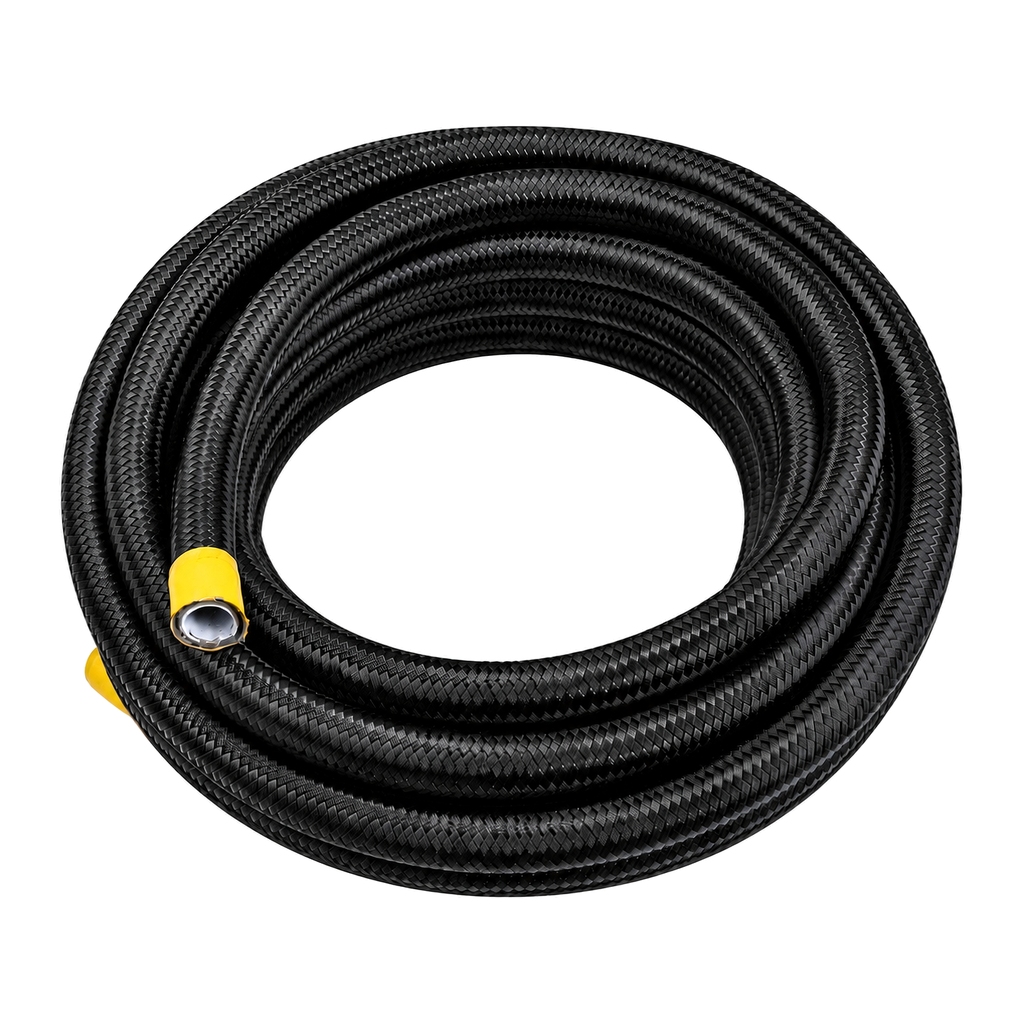
PTFE tubing and fluoropolymer hose products are engineered to handle demanding environments where standard rubber hoses fail. Chemical resistant tubing like PTFE is valued for its inert properties, temperature stability, and resistance to aggressive media. However, the superior material characteristics alone don't determine success. The hose diameter must align with flow velocity, pressure ratings, space constraints, and system architecture to deliver optimal performance. Many engineers underestimate how significantly diameter impacts overall system functionality, leading to undersized installations that create unnecessary pressure stress or oversized configurations that waste resources and space.
Understanding Flow Rate and Velocity Requirements
Calculating Your Required Flow Rate
The foundation of diameter selection begins with understanding your system's required flow rate, measured in gallons per minute (GPM) or liters per minute (LPM). Flow rate defines how much fluid must move through the teflon hose within a specific time period. Start by identifying the pump output or the application demand. For automotive fuel systems, this might be forty to eighty GPM. For analytical laboratory applications, it could be milliliters per minute. Once you know the target flow rate, you can calculate the minimum internal diameter needed to achieve optimal velocity within that hose section.
Optimal Velocity Parameters
Industry standards recommend maintaining fluid velocity between three and seven feet per second for most applications using PTFE tubing and chemical resistant tubing. Velocities below three feet per second create sluggish flow, potential settling of particles, and inefficient system response. Velocities exceeding eight feet per second generate excessive pressure drop, increase turbulence, create noise, and accelerate component wear. The optimal zone depends on application type. Low-viscosity liquids can tolerate slightly higher velocities than high-viscosity fluids. Fluoropolymer hose used in fuel systems typically operates at four to six feet per second for efficiency and longevity. Calculating the required diameter involves dividing your flow rate by the target velocity to determine the internal cross-sectional area, then converting to diameter measurements.
Pressure Ratings and Material Specifications
Matching Diameter to Pressure Class
Pressure capabilities in PTFE tubing and teflon hose increase with smaller diameters when wall thickness remains constant. A quarter-inch diameter teflon hose typically sustains higher pressure ratings than a half-inch diameter under equivalent wall thickness, because the smaller diameter reduces stress concentration on the hose material. However, this relationship creates a design challenge. You cannot simply reduce diameter to gain pressure rating without sacrificing flow capacity. The solution requires selecting appropriate wall thickness and reinforcement. Nylon-braided or stainless-steel-wrapped chemical resistant tubing provides pressure ratings that accommodate both small and large diameters. Understanding your maximum operating pressure is essential before finalizing diameter selection to ensure the complete hose assembly meets all safety margins and regulatory requirements.
Temperature and Chemical Compatibility
Fluoropolymer hose materials like PTFE exhibit exceptional thermal stability and chemical resistance across a wide operational envelope. However, the chosen diameter influences how effectively the hose manages these stresses. Thinner-walled small-diameter configurations heat more quickly at the fluid interface, potentially creating temperature gradients across the hose cross-section. Larger-diameter teflon hose with thicker walls distribute thermal stress more evenly. Similarly, chemical resistant tubing with adequate wall thickness maintains structural integrity longer when exposed to aggressive solvents or high-temperature media. The diameter you select should account for expected exposure duration and intensity. Fuel system applications often demand larger margins because they tolerate minimal degradation risk. Laboratory chemical transfer can sometimes use smaller diameters if exposure time is brief and controlled.
Space, Installation, and System Integration
Physical Space Constraints
Many diameter selection decisions face real-world constraints. Your assembly space might not accommodate the theoretically ideal hose size. Automotive engine bays, aircraft fuel systems, and industrial piping manifolds all operate under tight spatial boundaries. In these scenarios, you must identify the largest diameter that physically fits while maintaining minimum velocity requirements. PTFE tubing offers an advantage here because smaller diameters are possible without sacrificing chemical resistant properties. A smaller teflon hose diameter preserves routing flexibility and reduces installation labor. However, confirm that the resulting velocity remains within acceptable parameters. If space forces you below three feet per second, consider increasing length to maintain flow momentum, or adjust system pressure to compensate for pressure drop across a more restrictive diameter.
Connection Fittings and Thread Compatibility
The hose diameter must match available fitting sizes and system thread standards. Standard industrial fittings come in discrete sizes—quarter-inch, three-eighths-inch, half-inch, and so on. Chemical resistant tubing must terminate at fittings that securely engage the outer diameter without gaps or misalignment. Mismatched diameter-to-fitting combinations create leak paths, pressure instability, and system failures. Before finalizing your teflon hose diameter selection, verify that appropriate fittings, adapters, and connector assemblies exist for your chosen size. Some applications demand custom fabrication if standard sizes don't align with your specific requirements. Industrial suppliers maintain extensive databases of fluoropolymer hose assemblies in standard diameters, which is why keeping diameter selections within conventional ranges reduces lead time and cost.
Pressure Drop Calculations and System Performance
Predicting Pressure Loss Across the Hose
Smaller PTFE tubing diameters create higher resistance to fluid flow, resulting in greater pressure drop per unit length. This loss accumulates across the hose run and impacts downstream component performance. A system designed for 100 PSI inlet pressure that loses twenty PSI through an undersized teflon hose diameter leaves only eighty PSI for the application device. Many performance failures trace back to unaccounted pressure drop in the hose selection phase. You can calculate pressure drop using fluid dynamics equations or consult manufacturer charts specific to PTFE tubing. Fluoropolymer hose manufacturers provide pressure drop data across various diameters, flow rates, and fluid viscosities. Reviewing these technical specifications before purchase prevents costly field modifications and system redesigns. Generally, increasing the hose diameter by one standard size reduces pressure drop by approximately thirty to forty percent depending on flow rate and fluid properties.
Balancing Efficiency and Economy
Larger-diameter teflon hose reduces pressure loss and improves system efficiency but increases material costs and installation space requirements. Smaller-diameter chemical resistant tubing saves weight, space, and material expense but demands higher operating pressures to achieve the same flow. The optimal diameter represents equilibrium between these competing factors. For automotive and racing applications where fuel efficiency and lightweight design matter, slightly larger teflon hose diameters often deliver net benefits by reducing fuel pump load and improving cold-start responsiveness. Industrial applications prioritize reliability and longevity, making small diameter reductions worth avoiding. Evaluate your total cost of ownership, including energy consumption, maintenance frequency, replacement cycles, and system reliability impact alongside the direct hose procurement cost.
FAQ
What internal diameter should I choose for a fuel transfer system requiring 60 GPM?
For 60 GPM at optimal velocity of five feet per second, calculate the required area by dividing 60 GPM by 0.3208 (constant for feet per second conversion), which yields approximately 187 square inches. This corresponds to a three-quarter-inch internal diameter teflon hose. However, verify your specific fuel type viscosity and pump pressure rating, as racing fuel applications may benefit from half-inch PTFE tubing if space permits to reduce pump load and pressure stress on the chemical resistant tubing assembly.
How does wall thickness affect teflon hose diameter selection?
Wall thickness in fluoropolymer hose determines pressure rating independently from diameter. A quarter-inch PTFE tubing with thick nylon braid can achieve 5000 PSI, while thinner-walled chemical resistant tubing of the same inner diameter might only sustain 2000 PSI. Thicker-walled teflon hose increases outer diameter, which affects routing and space availability. Your diameter choice must account for the total outer dimension including wall thickness and any reinforcement materials to ensure the assembly fits your available installation space.
Can I use a smaller teflon hose diameter if I increase system pressure?
While higher pressure creates faster flow through smaller diameters, this approach generates excessive turbulence, noise, and accelerated component wear. PTFE tubing and chemical resistant tubing in undersized diameters at elevated pressure create dangerous conditions, potential hose rupture risk, and unreliable system performance. The recommended velocity range of three to seven feet per second exists for safety and durability reasons. Smaller diameter sacrifices should focus on space constraints, not pressure compensation.
 EN